
Op-Amp Experimentation 1: Op-Amp Basics
Op-Amp Experimentation 2: Basic Circuit Math
Op-Amp Experimentation 3: Op-Amp Applications
Op-Amp Experimentation 4: From Ideal to Real
Op-Amp Experimentation 5: Integrator
Op-Amp Experimentation 6: Differentiator
Op Amp Experimentation 7: PID Controller – coming soon
So we have talked quite a bit about “ideal” op-amps, but there are some important things to understand before starting a circuit design to amplify 5V into 500,000V and creating unlimited energy with a few op-amps. Now obviously the input impedance isn’t actually infinite, and the open-loop gain of an op-amp isn’t actually infinite, etc. But here is an important distinction that I, as a Mechanical Engineering and not an Electrical Engineering, took a while to fully grasp. The output of an op-amp is limited by – surprise surprise – the power supply! Let’s take a look at a previous example, the summing amplifier.
Summing Amplifier Real World Application

And the equation is  if all resistors are equal. Now let’s say I wired up the following circuit:
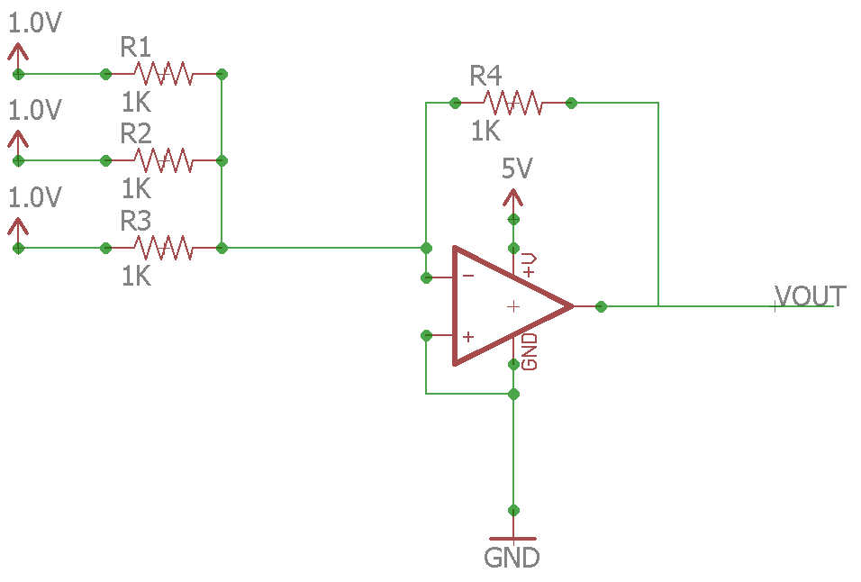
The output should be  right? Well here’s the problem, the lowest that the op-amp can output in theory is GND – or 0V. This means that the op-amp can not perform the summation we want. How do we solve this? Here’s how:
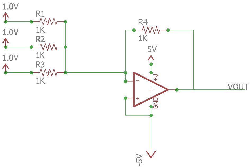
Just replace the GND with -5V! Now the lowest the op-amp can output is -5V, meaning the -3V should be no problem. But here’s the problem. Getting a dual supply (-5V and +5V, or -10V and +10V, etc) is difficult if you are working with microcontrollers. There is no -5V on an Arduino. So again, how do we solve this? The answer to this question took me a long time to figure out – not because it is very difficult, but because I didn’t have enough electrical knowledge to even know what to search for. But anyways, it turns out the answer is called a “biasing”. Well, actually in this case you could just use the non-inverting input instead of the inverting input, which would change our equation slightly, but anyways.
Biasing an Op-Amp
Now I searched far and wide for answers to using an op-amp with a single supply, and the information is readily available, however not very easily digestible for me. So I will try to explain it in a way that I wish someone explained it to me. An op-amp has limits on its outputs that are called the saturation limits. For a typical op-amp, the maximum output is roughly the max voltage of the power supply minus 1V, and the minimum output is the minimum power supply voltage plus one volt. So if you had a power supply that was +15/-15V, the max/min output would be +14V/-14V. Similarly a power supply of +5V/0V the max/min output would be +4V/+1V. Now there exists op-amps that classify themselves as “rail to rail” – this means that can reach much closer to the supply limits, often within 10mV. These specifications can be found in the datasheets.
When you have an op-amp configuration that will output a voltage that your supply doesn’t allow, you may need to bias the output. A bias is simply a shift in the output. For example, if you had an inverting amplifier setup that would produce anywhere from 2V to -1V, but you had a 0V-5V power supply, you would want to shift the output +2V, or bias the output +2V. This can be done very easily by simply applying +2V to the non-inverting input.
Remember, an op-amp can be setup in 3 main ways: Inverting Amplifier, Non-Inverting Amplifier, and Differential Amplifier. The rest of the circuits are build upon these three principles. So below are the methods used to bias an output for each of the three main configurations. But before that are two main methods of generating a bias voltage: voltage divider and voltage follower.
Generating a Bias
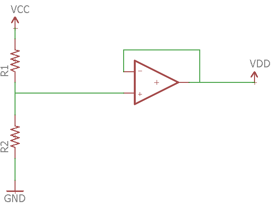
Voltage Divider

Here,  . This can become an issue though, because if there is a voltage applied to Vout or external impedance, it will affect the voltage.
Voltage Follower
Here the equation is the same, but the value for VDD will not change based on external loads. This is a much more accurate and stable way of doing things, and also reduces power consumption because the resistor value can be increased causing current through the resistors to be minimal.
Biasing an Op Amp
Inverting Amplifier

Vcc is the supply voltage, Vin is the signal, and Vout is the output
Note that the bias voltage is a voltage divider, and could be replaced with a voltage follower instead. However no current is allowed to pass into the op-amp, so the bias voltage shouldn’t change and therefore wouldn’t need a voltage follower.
Here the voltage at the non-inverting input is
 and the output voltage is

This gives full control over the output voltage range.
Non-Inverting Amplifier
Trick question, this can be easily solved with a summing amplifier since the voltage is already a positive output (assuming a positive input). There are ways of doing it, but I won’t bother with posting them here.
Differential Amplifier
This is the fun one, and the easy one.

Here Vbias is best provided with a voltage follower. Assuming R1 = R2 and R3 = R4 the equation comes out to:

So it is very simple to calculate how much of a bias you need, since the gain of the amplifier does not affect the amount of the bias.
Okay, next page we will actually build some of these and test them out. Enough theory for now.
Previous: Op-Amp Experimentation 3: Op-Amp Applications
Next: Op-Amp Experimentation 5: Integrator